
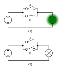
1.The given image shows two circuits: (1) with switches A and B in series, and (2) with switches A and B in parallel. Represent each circuit using Boolean logic operators, and draw the truth tables for both circuits to determine when the light bulb will be on.
2.Using the circuits shown in the image, design a lighting system for a room where Circuit (1) controls a security light and Circuit (2) controls a regular room light. Explain the conditions under which each light will turn on, and suggest a practical scenario for each circuit based on the switch positions shown.
1.
Answer:
- Circuit (1) – Series (AND Logic): For the bulb to light, both switches A and B must be closed (A = 1, B = 1). This is an AND operation: Output = A ∧ B.
Truth table:A B A ∧ B (Bulb) 0 0 0 0 1 0 1 0 0 1 1 1 The bulb is on in Circuit (1) because A = 1 and B = 1 (both switches are closed). - Circuit (2) – Parallel (OR Logic): For the bulb to light, at least one switch (A or B) must be closed (A = 1 or B = 1). This is an OR operation: Output = A ∨ B.
Truth table:A B A ∨ B (Bulb) 0 0 0 0 1 1 1 0 1 1 1 1 The bulb is off in Circuit (2) because A = 0 and B = 0 (both switches are open).
Description: This question helps students translate electrical circuits into Boolean logic, reinforcing Competency Level 4.1. The series circuit (AND) requires both switches to be closed, while the parallel circuit (OR) needs only one. Drawing truth tables solidifies their understanding of how logic gates model real circuits, and they can see why the bulb is on in Circuit (1) but off in Circuit (2) based on the switch positions.
2.
Answer:
- Circuit (1) – Security Light (AND Logic):
- Conditions: The security light turns on only if both switches A and B are closed (A = 1, B = 1). This represents an AND operation: Output = A ∧ B.
- Scenario: Switch A could be a master switch, and Switch B could be a motion sensor. The security light only activates if the master switch is on AND motion is detected. In the image, both switches are closed, so the security light is on, indicating that the system is active and motion has been detected.
- Circuit (2) – Room Light (OR Logic):
- Conditions: The room light turns on if either switch A or B is closed (A = 1 or B = 1). This represents an OR operation: Output = A ∨ B.
- Scenario: Switch A could be at the door, and Switch B could be near the bed. The room light turns on if either switch is flipped, allowing control from two locations. In the image, both switches are open, so the room light is off, meaning no one has turned it on from either location.
Description: This question applies Boolean logic to practical scenarios, aligning with Competency Level 4.2. Students learn to interpret the circuits as AND and OR operations and design real-world systems, such as a security light requiring two conditions (Circuit 1) or a room light with multiple control points (Circuit 2). The switch positions in the image help them analyze the current state of each system, enhancing their ability to connect logic to everyday applications.