

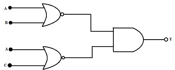
- For the first logic circuit shown in the image (top circuit), determine the Boolean expression for the output Y in terms of inputs A, B, and C, and draw the truth table to show when Y is 1.
Answer: - The second logic circuit in the image (bottom circuit) has inputs A, B, and C, and output Y. Imagine this circuit controls a sprinkler system where A represents a timer, B represents a soil moisture sensor, and C represents a rain sensor. Explain the conditions under which the sprinkler (Y) will turn on, and describe a practical scenario where this circuit’s logic is useful.
1.
Answer:
- Boolean Expression:
- First AND gate: A · B
- Second AND gate: A · C
- OR gate: Y = (A · B) + (A · C)
- Truth Table:
A B C A · B A · C Y = (A · B) + (A · C) 0 0 0 0 0 0 0 0 1 0 0 0 0 1 0 0 0 0 0 1 1 0 0 0 1 0 0 0 0 0 1 0 1 0 1 1 1 1 0 1 0 1 1 1 1 1 1 1
Description: The first circuit’s output Y is 1 whenever A is 1 and either B or C (or both) is 1, which can be simplified as Y = A · (B + C) using Boolean algebra. Constructing the truth table helps students understand how the AND and OR gates interact, reinforcing Competency Level 4.1. This exercise also teaches them to derive Boolean expressions from a circuit diagram, a fundamental skill in logic design.
2.
Answer:
- Boolean Expression for the Second Circuit:
- First AND gate: A · B
- Second AND gate: (A · B) · C
- OR gate: Y = (A · B) + ((A · B) · C)
- Simplified: Y = A · B (since (A · B) · C is a subset of A · B).
- Conditions for Sprinkler to Turn On:
The sprinkler (Y) will turn on when A = 1 and B = 1, regardless of C. In terms of the scenario:- A = 1: The timer is active (it’s the scheduled time to water).
- B = 1: The soil is dry (moisture sensor indicates watering is needed).
- C (rain sensor) doesn’t affect the output because the OR gate ensures Y = 1 as long as A · B = 1.
- Practical Scenario:
This circuit could be used in a garden irrigation system. The sprinkler should activate only if it’s the scheduled time (A = 1) AND the soil is dry (B = 1). The rain sensor (C) is included but doesn’t prevent the sprinkler from turning on in this circuit design, which might be a flaw. For example, if A = 1 (timer is on), B = 1 (soil is dry), and C = 0 (no rain), the sprinkler turns on, which is appropriate. However, if C = 1 (it’s raining), the sprinkler still turns on, which might not be ideal. This scenario encourages students to think about improving the circuit (e.g., by adding a NOT gate for C to prevent watering during rain).
Description: This question applies the second circuit’s logic to a real-world problem, aligning with Competency Level 4.2. Students analyze the circuit’s behavior, translate it into a practical context, and evaluate its effectiveness, fostering critical thinking. The sprinkler system example makes Boolean logic relatable, and the potential flaw in the design encourages them to think about how to modify the circuit for better functionality, such as incorporating a NOT gate for the rain sensor.